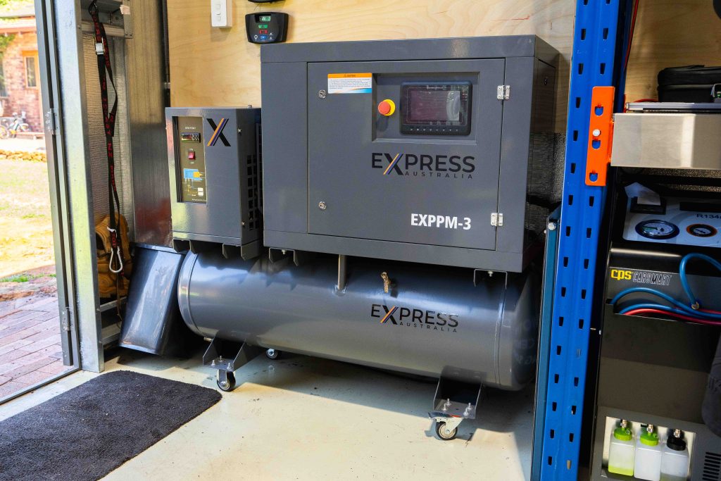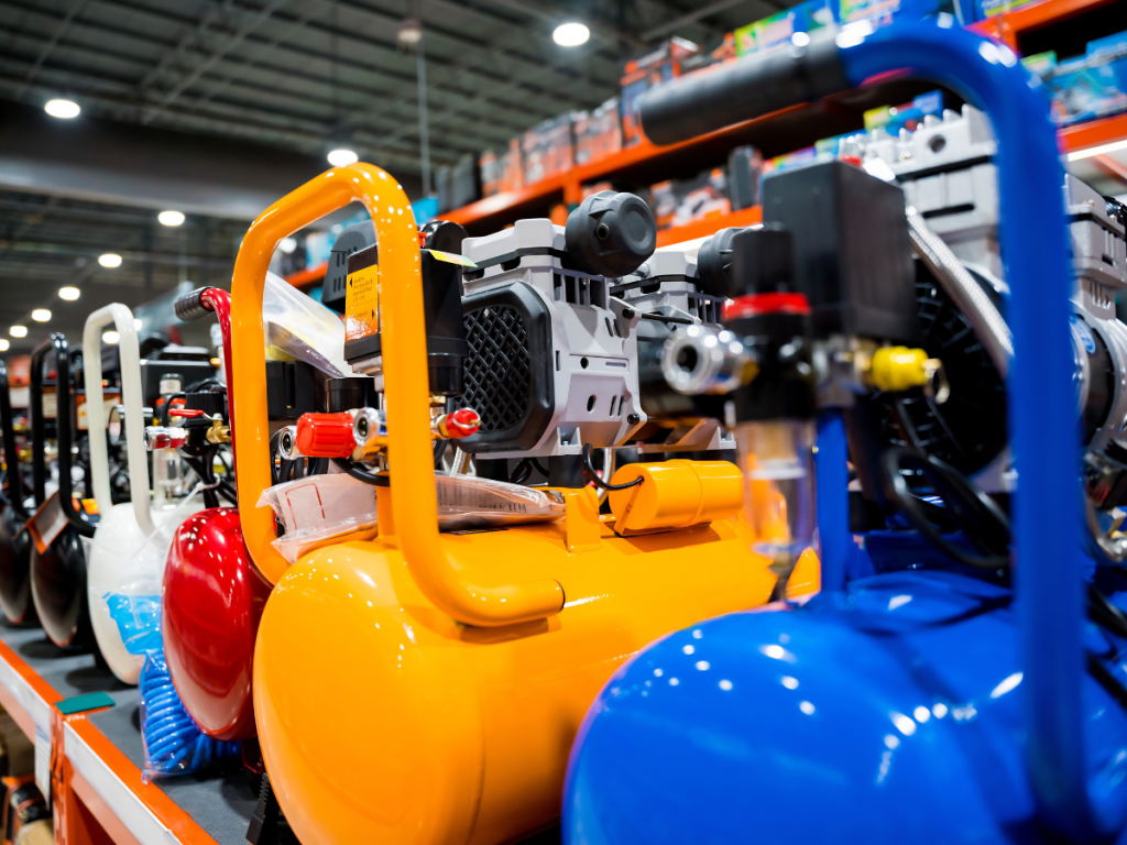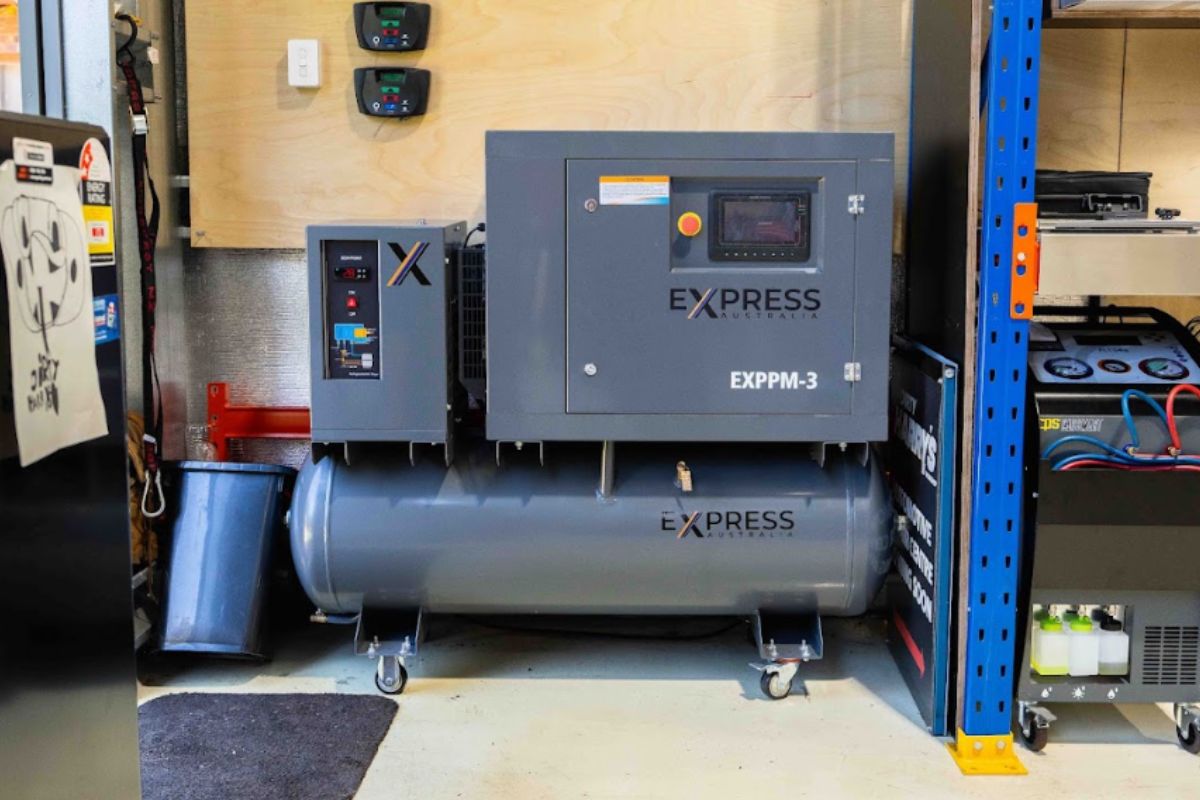
Many air compressor components work together to deliver a steady supply of compressed air to workshops, manufacturing facilities, mine sites and other industrial operations across Western Australia.
A rotary screw air compressor works as one connected system. Air moves through the intake, compression, separation, cooling and discharge stages, while oil circulates through the air end, separator vessel, filter and cooler.
In this guide, we’ll take you through how the main rotary screw air compressor components work, how air and oil move through the system, and the role each part plays in maintaining reliable performance.
PHASE 1: AIR INTAKE AND REGULATION
INLET AIR FILTER
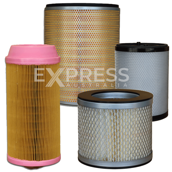
Atmospheric air first enters through the inlet air filter. This removes dust, dirt and other airborne particles before they reach the air end, helping protect the rotors, bearings and lubricant.
A blocked filter can restrict airflow, reduce output and increase strain on the compressor. Units operating in dusty workshops or mine sites may need more frequent filter inspections.
INLET VALVE OR LOAD-UNLOAD VALVE
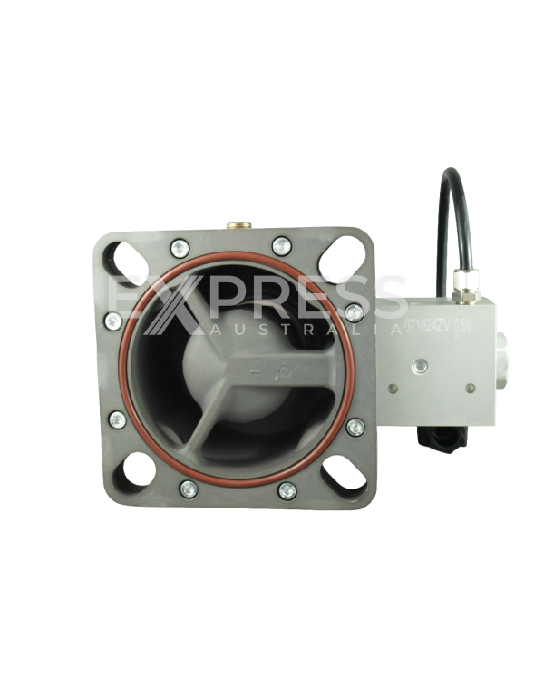
Filtered air then passes through the inlet valve, which regulates airflow according to system pressure and demand.
During loaded operation, the valve opens, and the compressor produces air. During unloaded operation, it restricts airflow. The motor may continue running, but the machine does not produce its full compressed-air output.
PHASE 2: THE AIR END AND COMPRESSION PROCESS
ROTARY SCREW AIR END AND INTERLOCKING ROTORS
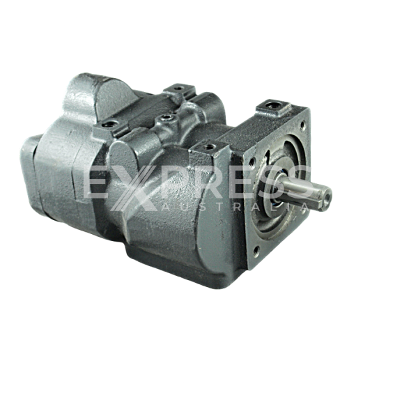
The air end is the main compression component. Inside it, male and female rotors turn in opposite directions. The shape of the interlocking rotors creates spaces that trap and move air through the housing.
The motor drives the rotors through a direct-drive, belt-drive or gear-drive arrangement. In a variable-speed drive compressor, motor speed changes to match air demand.
COMPRESSION CHAMBER
As the rotors turn, the trapped air moves along the air end. The available space becomes progressively smaller, increasing the air pressure.
Oil enters the compression chamber at the same time. It lubricates moving components, seals clearances between the rotors and housing, and absorbs heat generated during compression.
The compressed air and oil leave the air end together as a hot mixture.
BEARINGS, GASKETS AND SHAFT SEALS

Bearings support the rotors and keep them aligned at high speed. Accurate alignment maintains the small clearances required for efficient compression.
Gaskets and shaft seals retain lubricant, reduce air leaks and help prevent contaminants from entering the air end.
PHASE 3: AIR-OIL SEPARATION AND THE OIL CIRCUIT
AIR-OIL SEPARATOR VESSEL
The air-oil mixture flows into the separator vessel. Changes in airflow direction, internal baffles and centrifugal action remove most of the oil.
The oil collects at the bottom of the vessel, while the compressed air continues towards the separator element and discharge system.
OIL FILTER, THERMOSTATIC VALVE AND OIL COOLER
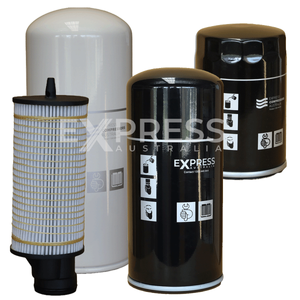
The separated oil must be cooled, filtered and returned to the air end.
The thermostatic valve determines whether oil bypasses the cooler or flows through it. Cold oil may bypass the cooler so the compressor reaches its correct operating temperature sooner. Once hot, the oil passes through the cooler to remove excess heat.
The oil filter captures contaminants before the lubricant returns to the air end. Component order varies between models, but the purpose remains the same: clean the oil, control its temperature and maintain circulation.
COALESCING OIL SEPARATOR ELEMENT
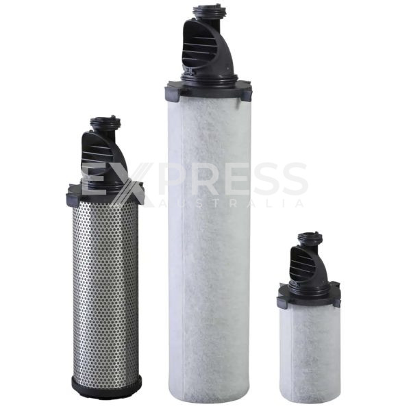
Compressed air still contains a fine oil mist after the first separation stage. The coalescing oil separator element captures these droplets and combines them into larger droplets.
A scavenging line returns the collected oil to the oil circuit. A blocked or damaged separator can increase pressure drop, energy use and oil carryover into downstream equipment.
PHASE 4: PRESSURE CONTROL, COOLING AND DISCHARGE
MINIMUM PRESSURE VALVE AND NON-RETURN VALVE
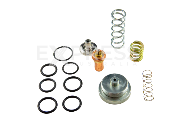
The minimum pressure valve maintains enough pressure inside the separator vessel for effective oil circulation and separation. It remains restricted during start-up and opens further once the required pressure is reached.
The non-return valve, or check valve, prevents compressed air from flowing backwards after shutdown. Some designs combine both functions in one assembly.
AFTERCOOLER
Compressed air leaves the separation stage at a high temperature. The aftercooler reduces its temperature before it enters the receiver, pipework or air-treatment equipment.
As the air cools, water vapour condenses into liquid, allowing the moisture separator to remove bulk water.
MOISTURE SEPARATOR
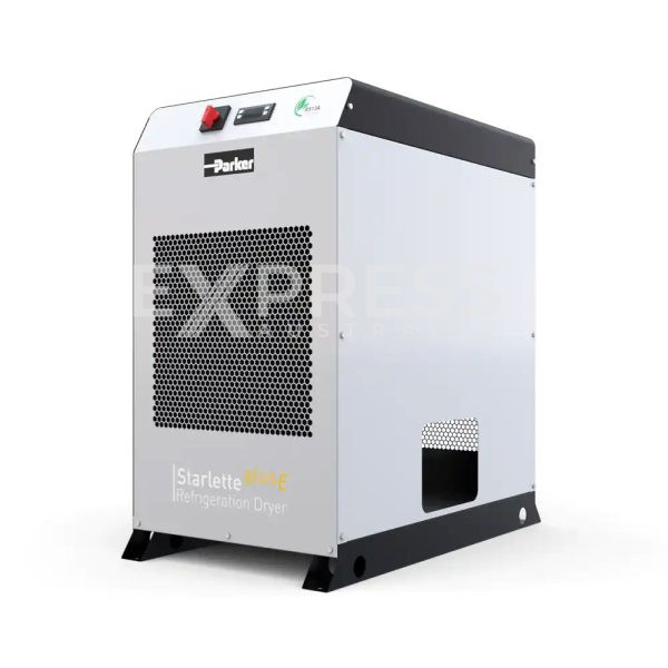
The moisture separator uses centrifugal movement or directional changes to remove condensed water droplets from the airflow.
It removes bulk liquid but does not provide the same moisture control as a compressed-air dryer. Applications requiring a lower pressure dew point generally need additional drying equipment.
FINAL COMPRESSED-AIR DISCHARGE
The compressed air leaves through the discharge outlet and may enter a receiver tank, distribution pipework or downstream air-treatment system.
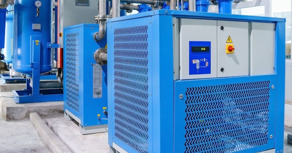
Depending on the required air quality, it may then pass through inline filters, refrigerated or desiccant dryers and other treatment equipment before reaching pneumatic tools or machinery.
Receiver tanks, dryers and many inline filters sit outside the compressor, although they form part of the complete compressed-air system.
PHASE 5: THE CONTROLLER, MOTOR AND ELECTRICAL SYSTEM
SYSTEM CONTROLLER
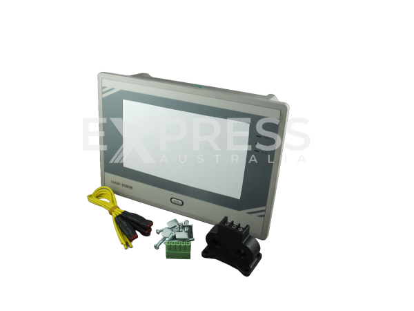
The controller manages compressor operation. It monitors pressure, temperature, motor status, running hours, service intervals and fault conditions.
It communicates with the inlet valve, motor and variable speed drive to adjust output. It may also issue warnings or shut the machine down when conditions move outside safe limits.
COMPRESSOR MOTOR AND VARIABLE SPEED DRIVE
The electric motor provides the power needed to rotate the air end.
A fixed-speed compressor runs at a set motor speed and usually manages demand through load-unload control. A variable-speed drive compressor adjusts motor speed to match the required air output.
This can reduce unloaded running and unnecessary power consumption where demand changes throughout the day.
SAFETY AND MONITORING COMPONENTS
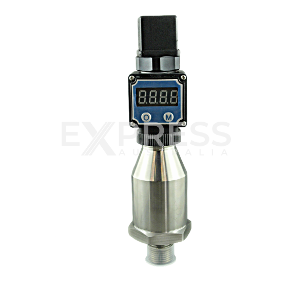
Pressure sensors, temperature sensors, relief valves, emergency stops and overload protection help protect the compressor from excessive pressure, heat or electrical load.
Safety devices should only be inspected, tested or replaced by suitably qualified technicians.
KEEPING THE SYSTEM WORKING RELIABLY
Every component supports the same continuous process. Clean air must enter the machine, the air end must compress it, oil must control heat and wear, and the separation and cooling stages must prepare the air for use.
Regular servicing helps keep the system efficient. Air filters, oil filters, separator elements, valves, seals and coolers should be inspected and replaced according to the manufacturer’s requirements and actual operating conditions.
If you are looking for genuine, aftermarket and OEM equivalent compressor parts for major brands, give our team a call today. Search by part number or contact our team for help identifying compatible components for your equipment.